opening

Regular reports of my grabber activity and that of others, plus information on QRSS software, hardware and technique that comes my way

Tuesday, June 14, 2011

Improvements to my air conditioning system as observed on the ON5EX grabber

Several nights ago I had my mept on 40m and recorded it's reception on the ON5EX grabber using SiteShoter then stitched the grabs together to see how I did over the long term.  I have described this technique previously on this blog.  Here's what it looked like:
So, what's this got to do with my air conditioning?  When we first moved to this QTH the air condx would cycle on and off on a hot summer day but as the years went by it got to the point of running continuously 24/7 and our electricity bill rose accordingly.  Over the winter we had an energy audit courtesy of the local power company and the auditor recommended we have our ductwork checked for leaks and add more insulation in the attic.  We followed his advice and as the temps began to climb into the upper 90's (37 C) earlier this month it was a relief to note the air condx was once more cycling on and off.  I meant to make a few measurements but haven't had time so far....until the night I recorded the above data.

My mept at the time was a QRP Labs kit which I have found to drift with changes in room temperature and I can see that drift on the ON5EX grabber. It shows the air condx to come on for 10 minutes then off for 10 minutes.  The change in temperature is several degrees F based on a previous calibration also describe on this blog.

Consider the irony.  I have without intending to do so remotely sensed the performance of my air conditioning system via a facility located in Belgium.

de w4hbk

Tuesday, May 24, 2011

FollowUp on Using WSPR Data

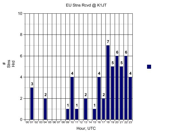
A few hours ago I checked the 20m WSPR data for the EU to NJ path during the past 24 hrs.....what a difference from the past weekend!  See for yourself:

Figure 1.  EU stations heard @ K1JT on May 21


Figure 2.  EU stations heard @ K1JT on May 24

Apparently condx were terrible over the weekend while my grabber was on 20.  The only dx station I heard was G6AVK and just for a few hours around 2300z.  If we had been on the past 24 hours I should have heard EU longer and probably louder.

The reason I'm interested in all this is that I've been thinking of moving my grabber to one of the higher bands during my local daylight  (1300z to 2300z) since that is usually when the dx comes thru to Florida.  But not being one to beat a dead horse I want to have some assurance of success.  My plan is to keep and eye on WSPR data as a guide to which bands and times to be QRV, particularly as a supplement to standard propagation predictions.

de w4hbk

Monday, April 18, 2011

Temperature Control for My Kenwood TS-440

Here's how to add a temperature controller to an older rig like my Kenwood TS-440.  Essentially you just make a copper sleeve for the master crystal, glue on a pair of heating resistors, a LM-35 temperature sensor and use a 4-wire cable to connect to the control circuit located outside the rig.  This is the same approach I described previously in Part 1 of my series on temperature controllers.

The main requirement it that the frequency of the receiver be controlled by a single master crystal as in the TS-440.  Older radios with multiple crystals used for the various hetrodyning stages will be too awkward to adapt because a separate controller would be required for each one.*

The TS-440 is actually pretty challenging with respect to cramped quarters.  The crystal is located in the middle deck of a stack of 3 PC boards with very little room for the compact sleeve that fits around the xtal....but it just works.  Figure 1 shows what we're up against.


Figure 1.  Location of master crystal in the TS-440


The front of the rig is at the top of the photograph.  Note the upper deck has been swung up to allow access to the middle deck where the crystal is located.  The small chassis to the right contains he outboard temperature control circuitry.  The cable connecting the two is a 4-conductor type from an old modem line.

Figure 2.  Close-up of Copper Sleeve Installed on Crystal


Figure 2 is a closer view of the crystal location showing the copper sleeve installed.  The heating resistors are on the left and right sides of the sleeve and if you look carefully you can see the TO-92 case of the LM35 in between.  Note how close the crystal is to the shield of one of the PLL's...there is only a few mm spacing and no room for Styrofoam insulation as I have used with other TC's.

Figure 3.  Case Closed

Figure 3 shows the case closed back up.  Along the front of the controller are, L to R, temperature control pot, LED indicator, Temp or drive voltage switch and RCA plug for voltmeter.  Figure 4 shows everything set up and operating.  When power is first applied to the controller the LED glows brightly then gradually dims to a steady value to indicate regulation.

Figure 4.  System in Operation


How does it perform?  Bottom line, the frequency is stable enough for long duration stacking work up to 6 hours.  When I monitor WWV the variation over a day is +/- 1 Hz when the wx is nice enough to leave the windows open 24/7 and outdoor temperatures vary by 15 degrees F.  I adjusted the operating temperature to 125 deg F (52 C) which is the measured turn-around point for the TS-440 crystal.  I determined this by varying the temperature with the pot and noting the point where temperature quits decreasing and starts increasing again....see Part 1.  The ceiling fan has a noticeable effect on temperature variations and when I'm really serious about stacking I leave it on low speed to keep the air in the shack well stirred.

de w4hbk


Friday, April 15, 2011

WA5DJJ's new mept

Dave, WA5DJJ, has brought together some ideas to produce the ultimate QRP Labs mept modification that is stable in both time and frequency to make it adequate for image stacking.  To jog ur memories, it is possible to stack successive grabs using an astrophotography program called Rot'N'Stack to pull really weak signals out of the noise. To do so the message must appear at exactly the same place on the grab from one to the next, i.e., must be stable in both time and frequency. The SNR improves as the square root of the number of images stacked.  I'll leave it to Dave to describe his mods but basically it involves using the 4-component temperature controller I described in Part 2 of my series here on this blog and the change to a PIC keyer designed by Mike, N0QBH.  This latter mod allows a 32 kHz clock xtal to stabilize the timebase.

Last night I recorded the signal from Dave' new rig and the results were nothing short of phenomenal.  Over a period of 4 hours he drifted only 1 Hz, which as I told him could easily be my rx...the wx is wonderful now and we're leaving the windows open in the shack resulting large temperature changes.  The times base was virtually jitter free and started exactly on time every 10 minutes.  Figure 1 shows his signal as recorded on my 5 hr grabber. 

Figure 1.  5 hour grabber showing Dave's signal


Each of the short pulses represents a 10 minute grab as normally seen on my regular grabber.  I used 25 of the 10 minute grabs, going from 0717z to 1114z, in the Rot'n'Stack stacking program to produce the averaged image shown in Figure 2.  Even though Dave's signal was strong and didn't need stacking to bring it out of the noise, this provided an acid test of his rig's stability in both time and frequency.  The degree to which it is off will appear as blurring or jitter.  The timing is virtually perfect and what little frequency blur there is is caused by the 1 Hz drift over the recording time.

Figure 2.  Stacked average of 25 grabs


In addition to Dave's signal, several surprises popped out of the noise.  VK6JY is using a stabilized Hewlett-Packard signal generator which responded quite well to the stacking process.  There was no hint of N4FRE or ZL1EE even on the 5 hr grab which has a much better SNR than the 10 minute grabbs.  Both have highly stabilized signals via atomic clocks and/or GPS.  FRE usually drops completely out this time of night and if any of his signal was left it was completely obliterated by P29ZL.  It's ironic to be using sophisticated software and equipment to extract a 'local' station out from under one so far away (with an antenna  up in a banana tree no less).  However ZL's mept is not stabilized in time and thus averages at the same time FRE's builds up.  QRSS does have it's moments.

Congratulations to Dave on his new rig.  It looks like all the mods can be added directly to the rig so it will still fit in an Altoids tin.  Now if everybody adopts those mods then they too can pop out of the noise when stacking is applied.

de w4hbk

P29ZL


The signal of P29ZL caught my attention soon after it's appearance on my grabber last month for two reasons.  First, it appears almost every night for about 5 hours, very strong and easy to copy.  But equally interesting is the extreme multipath/Doppler effect which is always present for at least part of the time.  Tim's mept, from the WA5DJJ Labs,  runs 250 mW to an inverted V hung in a 25 foot banana tree.  Figure 1 is a 5 hour grab from a few nights ago and is typical of what I see every night:  note in particular the considerable fuzziness of the signal between 1000 to 1100z.  Figure 2 is from the 10 minute grabber and shows the effect in more detail.  Other signals from out that way, most notably VK6JY show just a bit of broadening but nothing like that from P29ZL.

Figure 1 - P29ZL on the W4HBK 5 hr grabber, 12Apr11, 30m 


Here is my understanding of the multipath/Doppler effect.  As the signal passes through the ionosphere it may be partially refracted back towards Earth but a part may continue on to find another refracting region for a second signal, an so on.  At the same time multiple hops can occur with the results that a number of signals can arrive at the receiving antenna.  But for a Doppler shift to occur these various regions must be moving relative to one another.  Without this relative motion the signals arriving from the various paths would be at the same frequency but differing in phase to cause fading due to interference.  Other phenomena such as ionospheric irregularities and turbulence can also contribute a continuous broadening....visualize an eddy where some of the electrons are moving towards and some away from the path of propagation.  I've noticed that most writers of the scholarly articles end up stating how complex is the ionosphere....as the kid next door says to me sometimes. "Well, Duhhh!"

Usually the M/D effect is relatively simple with just 2 noticeable frequencies and I see this almost every day on one signal or another as the band is changing around sunrise/sunset.  What makes the fuzz on P29ZL's signal unique is that it's a daily occurrence with a near-continuous broadening, usually towards a higher frequency which would indicate the path length is decreasing.  Sometimes one or two distinct frequencies appear out of the continuum.

Enough for now about this most interesting signal but I will be keeping an eye on things and doing a bit more reading.

de w4hbk

Friday, March 18, 2011

Temperature Controllers for QRSS Part 3

Here is info on another temperature controller used by PA0TAB which uses discreet components mounted at the crystal.  I'll quote the email:

"Hi Bill
I use another oven. Very simple. article Elektron 1976-6
See attachments. The picture is one of my versions
I feed from 12V stab and at the picture a 2N2905 is the PNP
I used 2 composite carbon resistors (Allen Bradley)
because they have flat surface. I use tin plate as mounting.
I soldered the Xtal, the 2905  and one contact of the NTC direct to the tin plate.
So they have a good thermal contact.
For 12v you have to increase the feeding resistor to the NTC thermistor.

I have also a version with one heating resistor of 4w 82 ohm ceramic
and a BD136 PNP (TO126 housing) also soldered
I use a styrophor isolation

I uxe an electronic thermometer and a mA meter to adjust.
Then I relace the potmeter by a fixed resistor
Temperature is adjustable about 90 til 130 degr F I use 110 degr.F.
I measure the temp amd the current. When the current goes down and the temp is to low decrease the potmeter til you have the right temperature.
Wait half an hour and check temp. If it is ok you could replace the potmeter by an equal resistor."

73 Johan pa0tab

Temperature Controller Used at PA0TAB

I recognize the two transistors as a Darlington pair and that makes me think of the op amp circuit I use (Part 1) but without the op amp...and why not.

Thanks for sharing, Johan.

de w4hbk

Thursday, March 17, 2011

Temperature Controllers for QRSS Part 2

Here is another temperature controller I've been trying out on my QRP Labs 80m MEPT.  It consists of just 4 components which are all mounted on the crystal.  Considering the small size of the crystals in the QL rigs this is quite an achievement.

 Figure 1.  Simple Temperature Controller


I found this circuit at a site devoted to Barometers, of all things.  You may well ask what is a TL431?  It is a programmable Zener diode.  Whatever voltage you place from the cathode to the connection coming out of the side will make it a Zener of that voltage.  It covers a range of 2.5 to 36 V.  The point where it starts to work, 2.5 V, is what we take advantage of to use it in a temperature controller.  Simply choose resistor values along the left side to make 2.5 V at the control electrode and it will switch on as the temperature drops below the set point and off as it goes above.  NTC thermistors are produced to a standard calibration curve and this is it for the NTC103 Thermistor:

Figure 2.  Calibration Curve for NTC103 Thermistors


On the above schematic the values not in ( ) are those of the original article and those in ( ) are the ones I selected based on a 9 V source and an operating temperature of 120 deg F/48.5 dec C.  From the curve in Figure 2 the resistance of the thermistor at 48.5 C is 3846 Ohms from which I calculated the other resistance to be 10k.

I installed these components on the short crystal in the new QRP Labs 80 kit which I was soldering up at the time.  Note that only two leads are required for the 9 V source and can be taken off a convenient location on the QL board.   Figures 3 and 4 shows what this looks like and Figure 5 shows the crystal assembly installed in the QRP 80.  I placed a 1 cm thick slab of Styrofoam between the crystal and circuit board as part of the thermal insulation.  To complete the insulation I whittled out a matching block of Styrofoam to place over the top.  When soldering up the QRP 80 it helps to move aside some of the components surrounding the crystal to accommodate the Styrofoam insulation.

Figure 4.  Connection of Components


It seems to work as well as the controller I described in Part 1.  When switched on the frequency quickly drops to a steady value and remains there for hours on end.  The big advantage is that no external circuitry is needed.  This is the way I plan to go when I build future MEPT's.

Before closing this post I'll mention yet a third temperature controller which is used by Johan, PA0TAB.  It consists of discreet components, two transistors and four resistors, which can be mounted on or at the crystal.  I'll describe that in a future post.

de w4hbk