A while back I did some tests with VK1OD to compare antennas using an automatic antenna switch he had devised for antenna testing.
I made a version of Owen's antenna switch which can be controlled by the QRS keying program which I use to key my mept via the computer's serial line. In the experiment described in this post it is being used to switch in an attenuator so I can transmit different power levels on the Mark and Space of the QRSS FSK signal.
Here's the schematic,
The driver transistor is located in my mept box and connected to the A/B switch box by a twisted pair. DTR is the DTR line of the serial cable coming from the computer. My mept is also keyed from this connection via another driver transistor
Here's a picture of the resulting keyer:
The attenuator is an L design with 50 Ohms to ground and a series resistor of 100 Ohms between A and B to give an attenuation of 10 dB. You can see where I tack-soldered in parallel resistors to reach 10 dB as measured using Spectrum Lab. The twisted pair on the left is the keying line from the serial port and there is an LED to indicate when antenna port B is switched in.
When used with the QRS keying program the switch automatically reduces the 1 W signal to 100 mW so one is on the Mark and the other on the Space.
The other use for this switch will be to compare antennas, my next project.
I have found the 10 dB comparison most illuminating. I seldom run my mept but when I do I generally use 1 W because I'm interested in observing propagation and want to ensure results. But, I often wonder what my signal would have looked like at the typical QRSS power level of 100 mW. Now I know. More often than not the 100 mW level is in the noise compared to the 1 W and would have required image stacking to identify the call. It's not just a matter of power because of other factors such as the grabber's antenna and local noise and how the waterfall display is set up.
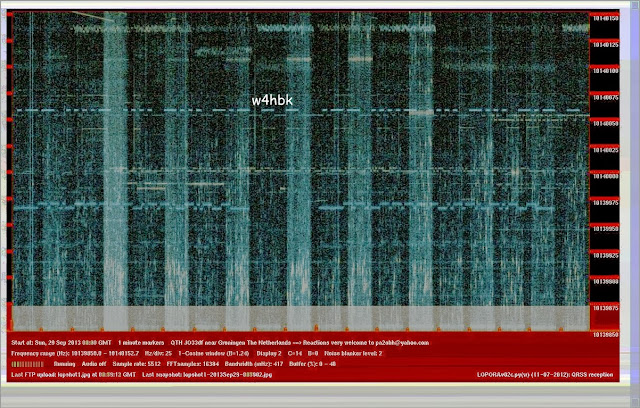
Here's an example taken from PA2OHH's grabber. In the first image which is a single grab the 100 mW Space is barely discernible and not clear enough to ID the call which is clearly seen in the Mark:
Here's a stacked image of multiple grabs from the same grabber:
Now you can see the 100 mW Space quite clearly and read the call in un-cw. I use this technique often on 40m where the 'barefoot' mepts don't make it out of the noise well enough to be identified.
It's no surprise that a 10 dB power gain makes a big difference but if you can read the lower power level then the gain is not very impressive. It's when the lower power is not visible at all and them emerges from the noise to be readable at the higher level that the difference is most impressive.
de w4hbk


No comments:
Post a Comment